In one line: A diagram of what a system must do, in what order and with what logic, drawn before deciding how or with what hardware it will be done.
Core idea
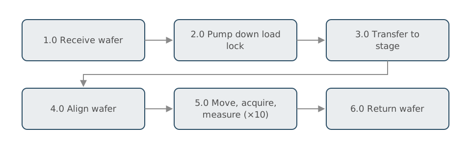
Functional analysis separates the system’s functions from its physical solution. A functional flow block diagram (FFBD) shows the functions as numbered blocks connected in sequence, with logic for parallel paths, alternatives and loops. Because it is solution-neutral, it lets a team agree on the work the system must perform, and then allocate those functions to subsystems, people or software. It is one of the standard techniques in the NASA and INCOSE handbooks [1].
How it works
- Blocks: each block is a verb phrase, such as load wafer, align wafer, measure feature.
- Numbering: levels decompose; function 3.0 expands into 3.1, 3.2, 3.3 on a lower-level diagram.
- Logic gates: AND (all paths happen, possibly in parallel), OR (one path is taken), and loops for repetition.
- Flow: arrows show sequence, not physical connection.
- Allocation: once the flow is agreed, each function is assigned to a subsystem. The resulting interfaces can be checked with an N-squared (N²) diagram, a matrix with subsystems on the diagonal and the data or material they exchange in the off-diagonal cells.
- Add time and the FFBD becomes the backbone of a timing analysis (see Throughput and Timing Analysis).
In practice
FFBDs are useful well beyond aerospace. Drawing the functions of a familiar device, such as a thermostat, a coffee maker or a test station, before discussing components often reveals that two people meant different things by “the system.” In software-heavy products, the same exercise shows which functions are done in software and which in hardware.
Questions to ask yourself
- Can I describe my system’s top-level functions without naming any hardware?
- Which functions could run in parallel instead of in sequence?
- Which interfaces appear only once functions are allocated to subsystems?
Connections
- Adds time to become: Throughput and Timing Analysis. Process home: Systems Engineering Process.
- Business cousin: Business Process Mapping. Physical counterpart: Product Architecture.
- Capabilities exercised: Communicating and Advocacy, Connecting Across Disciplines.